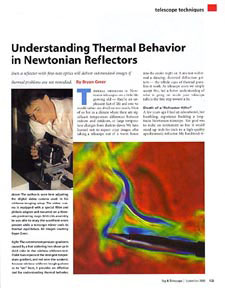
Understanding thermal behavior in Newtonian reflectors |
| by Bryan Greer |
| Originally posted Sept. 2000. Last updated October 19, 2023 |
Home
Telescope Thermodynamics
Sept. 2000 Sky & Telescope magazine companion web site
May & June 2004 Sky & Telescope magazine companion web site
Using fans with a Newtonian telescope
Tips on attaching a temperature probe to your telescope
Optical Miscellany
Try this at home!
How atmospheric seeing affects telescopes with different focal ratios
Animated focal plane illumination map
Properties of various mirror substrate materials
Adventures in collimation
 Video download page for my September 2000 Sky & Telescope article.
For a full description of these videos, and more on how they were made, please refer to the September, 2000 issue of Sky & Telescope magazine (download pdf link).
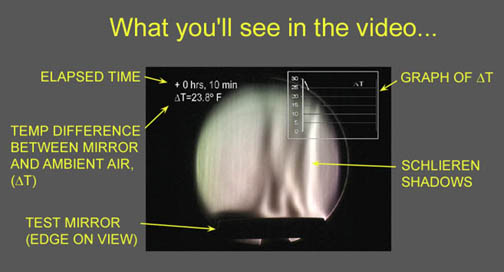
These are full motion video files that the still images in the article "Understanding Thermal Behavior in Newtonian Reflectors" were made from. Watching the schlieren shadows in full motion video helps to appreciate the true nature of these complex flows. All of these videos have been produced to play back at normal speed.
There is a high quality and lower quality (i.e., more MPEG compression) version of each video. They are identical except for their playback quality and file size. Choose the one appropriate for your download speed. (Unfortunately, not all of the superimposed text and titles are clearly readable on the lower quality versions.)
October 2023 update: In the past 20+ years video codecs and Internet speeds have changed considerably. I have (finally) updated the video files below to be compatible with modern browsers and players. The resolution of the video is still stuck in the 1999-era (640x480 resolution), but it's a simpler one-click process to view them now.
|
Description
|
|
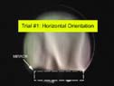 |
Schlieren cooling trial with mirror horizontalA 6" diameter, 1" thick, Pyrex mirror cools from an initial temperature difference of 28.4 degrees F, while lying flat (edge-on view of the mirror). The shadows represent where light has been refracted from its intended path by the thermal gradients. This qualitative test allows us to develop a more intuitive feel for what is going on inside the telescope at various stages of the cooling. It takes over two hours for the mirror to cool for this indoor test (the ambient temperature is a constant). Under real conditions outside at night, the mirror has even more difficulty tracking the falling ambient temperatures. |
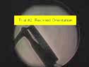 |
Schlieren cooling trial with mirror reclinedThe same mirror cools from 68 degrees F while in a reclined position. Note the very strong boundary layer hugging the surface of the mirror initially. Even after two hours, the boundary layer exists. |
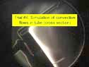 |
Simulated tube wall interaction with no tube ventsThis video is a vivid demonstration of why it's important to size your telescope tube sufficiently larger than the mirror. As the primary mirror cools, the rising thermal currents collect on the upper tube wall and partially remain in the optical path. The effects of this can be easily seen in a star test. |
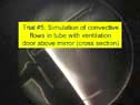 |
Simulated tube wall interaction showing how a well placed tube vent can duct away thermal currentsA small vent located in the tube wall above the primary mirror does seem to be at least partially effective at ducting the thermal currents out of the optical tube. There are problems with this solution, however. While the vents seem to improve the image when the mirror is rapidly cooling, they can hurt the image when the mirror is closer to ambient by disturbing the boundary layer. See the Sky & Telescope article for more on this. |
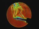 |
Rainbow schlieren test demonstrationThe rainbow schlieren technique permits quantification of wavefront errors caused by thermal currents. The different colors represent the degree to which the wavefront has been distorted(1). The red regions are no distortion, yellow and green are modest distortion, and blue and purple are the most refracted areas. Here is a brief demo video showing how the heat from a human hand, an exhaled breath, and a soldering iron distort the wavefront. A 6" f/10 spherical mirror is being tested. |
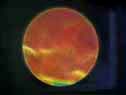 |
Rainbow schlieren trial of a mirrorThe rainbow schlieren test makes it possible to quantify the wavefront errors caused by the warm boundary layer hugging the face of the primary mirror. This video is excerpted from a 1-1/2 hour long cooldown trial, with an initial temperature differential of about 14 degrees F. Errors in excess of 1 wavelength peak-to-valley are common early on. Even after an hour, with the mirror about 5 degrees above the ambient air temperature, errors of 1/10th to 1/2 wavelength peak-to-valley over the mirror's surface are still typical. Unfortunately, this situation is common in mid-sized Newtonians without any active cooling. |
(1) The colors in the rainbow schlieren images do not directly represent the peak-to-valley wavefront error. They actually represent degrees of transverse aberration, or how much the light beam has been deflected. The transverse aberration is directly related to the slope of the wavefront error. The actual wavefront error is then derived by mathematical integration of this slope.
Return to Telescope Optics Topics.