Using fans with Newtonian telescopes |
| by Bryan Greer |
| Originally posted June 2005. Last updated Oct. 18, 2010. |
Home
Telescope Thermodynamics
Sept. 2000 Sky & Telescope magazine companion web site
May & June 2004 Sky & Telescope magazine companion web site
Using fans with a Newtonian telescope
Tips on attaching a temperature probe to your telescope
Optical Miscellany
Try this at home!
How atmospheric seeing affects telescopes with different focal ratios
Animated focal plane illumination map
Properties of various mirror substrate materials
Adventures in collimation
Introduction
 The resolution of a Newtonian telescope will improve by forcing ambient airflow over the primary mirror, usually with one or more small fans. When the optical face of the mirror is even 1-2 ºC (2-3 ºF) or more above the ambient air temperature, observable image degradation will exist. (My September 2000 Sky & Telescope article describes how this was quantified using the rainbow schlieren test method.) The wavefront will be deformed as it passes through temperature gradients near the face of the primary mirror. For most locations on Earth, even a small Newtonian's primary mirror will not track the falling nighttime temperature closely enough unless fans are used.
Fans have three benefits. Most importantly, they increase the rate of heat loss from the primary mirror. This results in the mirror being able to track the falling nighttime temperature more closely, as well as reducing the initial cool-down time when the scope is first taken outdoors.
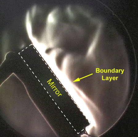
Another benefit is possible when fans are directed at the front face of the mirror where they can scramble the optical structure of the boundary layer. The boundary layer is a thin layer of warm air hugging the mirror's entire outer surface. All of the convective heat transfer from the mirror to its surroundings takes place within this layer. The portion of the boundary layer on the front face of the mirror is where the image degradation occurs. Chopping up the structure of the boundary layer has the effect of restoring high resolution to the image at the modest expense of imperceptibly increasing veiling glare.
Finally, fans on the front of the mirror will discourage dew from forming. The kinetic energy of the forced airflow makes it harder for seeds of condensation to form.
While fans do reduce the duration of the initial cool-down period, this is not their main purpose. The night air temperature is constantly falling, and the mirror cannot track along with the ambient closely enough without forcing airflow over the mirror. Thus, the fans should be left on throughout the observing session.
Adding fans comes with potential drawbacks. Fans can induce microvibration into the image. This can be avoided if you're aware of the most common installation mistakes. Also, if you own a push-around Dobsonian, its very simplicity is probably something you appreciate. Adding fans necessarily means adding wiring and a battery. This may be an unwanted addition to your already burgeoning astro gear. However, it's increasingly common for even Dobsonian telescopes to have other field power needs, so many observers are already taking a battery out with them.
 More Is Not Always Better
When determining how to use fans for your telescope, one goal is to use the least amount of air flow needed that will still achieve a high rate of heat transfer out of the glass. However, you quickly reach a point where more airflow is no longer beneficial, and only adds to vibration problems.
The graph to the right shows that even modest amounts of airflow forced over the mirror's rear surface significantly improves the heat transfer rate out of the mirror. Even using a small 25 mm (1") fan rated at only 8 cubic feet per minute of airflow results in a marked increase in heat transfer out of the mirror. The cooling curves for the larger fans begin to bunch up and lay on top of each other, which indicates there is no additional heat loss compared to the smaller fans. As an approximation, it appears a 20 to 25 cfm fan would be sufficient for each side of this particular 10-inch mirror.
I have tested other mirror sizes in this manner in order to make the recommendations shown in the table below. If your exact mirror size is not listed, interpolating between these values will not lead you too far off the mark. (It should be apparent from the graph there is wide tolerance in making these estimates.) Note that these airflow values are for each side of the mirror.
|
Mirror Size (Pyrex)
|
Airflow Requirement
(per side) |
|
6"
|
10-15 cfm
|
|
8"
|
15-20 cfm
|
|
10"
|
15-25 cfm
|
|
12.5"
|
20-30 cfm
|
|
16"
|
30-45 cfm
|
The reason for the limit on the fan's cooling ability is that heat transfer within the glass itself becomes the bottleneck. Glass conducts heat poorly which limits the rate of heat transfer from the interior of the mirror to the outer surface. This also explains why the thickness of the mirror is more important than the diameter or mass in determining how well the mirror will track the falling ambient temperature. The path of the heat flow is predominantly from the center regions of the glass directly to the nearest outer surface.
Fan Installation Schemes
Rear-mounted cooling fans
Adequate equilibrium can be reached with forced airflow over only the back of the mirror if it is thin enough. The front surface temperature will track the falling air temperature closely enough even though most of the heat is being drawn out of the mirror's rear surface. Rear fans work well for mirrors that have a thickness of approximately 1-1/2 inches or less. This is a fuzzy criteria, as it depends to some degree on where you live (as described in the next section).
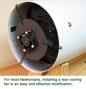 Given how easy it is to install a rear-mounted fan on most scopes, they should be the first fan installed before attempting more challenging frontal fans. Even in applications where a front-blowing fan is needed, you should still take advantage of cooling from the rear.
Perhaps the simplest method for installing a rear fan is by suspending it behind the cell with elastic bands. (Attaching the fan to the mirror cell is a mistake!) I prefer this method not only because it's simple, but also because it almost guarantees you won't have a vibration problem. With a quick connector in the wiring, it is easy to remove or reverse the fan in seconds. After playing with heavy rubber bands and metal springs, my current favorite elastic member is a hair band. These are essentially miniature bungee cords, and are quite robust. I've yet to see one break like rubber bands sometimes will.
When using a rear-mounted fan, you have a choice of airflow direction; blowing onto the back of the mirror, or sucking air out the bottom of the tube. Unless the bottom of your tube is closed and carefully ducted, blowing the air stream at the mirror will be more efficient (i.e., a smaller fan can be used to get an equivalent cooling effect). In practice, this slight advantage is almost meaningless, and other more pragmatic considerations take precedent. If you regularly observe from a dry, dusty, location, consider pulling air out the bottom of the tube to reduce the accumulation of dirt on your optics.
Front-blowing fans
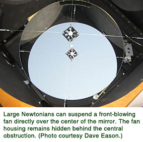 For thicker primary mirrors, there is benefit to adding front-blowing fans along with the rear fans. Exactly how thick your mirror can be before needing front fans depends on where you live, as it is a function of how fast your nighttime temperatures usually fall (see temperature profiles of cities). I live in the Midwestern part of the United States, and a small fan blowing on the back is sufficient for mirror thicknesses up to about 1-1/2". Mirrors up to about 2" to 2-1/4" thick need rear and front fans. For most locations, mirrors over about 2-1/4" thick mirrors won't adequately track the falling temperatures regardless of your fan configuration. In these cases, front-blowing fans are necessary to not only remove heat, but also to scramble the boundary layer. When using front fans for this purpose, you will need considerably more airflow across the front than what was recommended to just maximize heat loss.
You are hereby warned that a vibration-free front fan installation is more difficult to implement than a rear fan. Mounting fans directly to the tube of a solid tube style telescope is a sure way to induce microvibration in the image. Even an attempt to isolate the fan with a foam gasket is usually only partially successful. For solid tube telescopes, a good way to install a front-blowing fan right into the tube wall is to mount the fan to a thin, elastic, sheet of rubber (or even stretchable fabric such as Spandex®). The membrane diameter should be about twice the size of the fan itself, and have a plastic frame around the outside to provide a means to attach it to a cut-out hole in the tube wall. This method works well for fans up to about a 40 mm housing size. (Don't try to install a common computer power supply fan as a front-blowing fan.) If you need more airflow, use multiple fans instead of a larger one.
Truss tube telescopes have an easier time installing front-blowing fans since there is usually ample room around the mirror box to locate the fans. The heavy wooden structure also absorbs more vibration than most solid tubes do.
If you have a telescope with a thick mirror, but don't want to go to the trouble of installing front fans, your scope will still benefit by installing just rear fans. Cooling from the rear will still still reduce the temperature difference on the mirror's front, which in turn reduces the refracting strength of the boundary layer.
 Baffling the fan
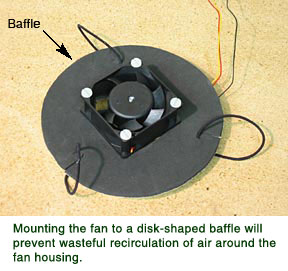
You can get more airflow out of a given size fan by ensuring the fan is properly baffled. Baffling a fan simply means the inlet and outlet regions around the fan housing are physically separated. Without baffling, a fan is less efficient (i.e., you'll get less airflow than its rating), as a portion of the air stream is continuously recirculated back around to the inlet side.
If you are mounting the fan to a surface of your telescope, this baffling requirement is taken care of by that surface itself. Fans that are suspended in space by elastic members will require a separate baffle. This can be done by simply mounting the fan to a flexible disk that is an inch or two larger than the plastic fan housing. You can also use the baffling disk as a more convenient location to attach the elastic members to.
Fan Vibration
Detecting vibration
Microvibration in the image frequently goes undetected. The best way to detect it is by examining the Airy disk of a bright star at high magnification, and switching the fans on or off. The size of the Airy disk should not change. This test requires magnifications of at least 30X your aperture in inches (the May 2004 Sky & Telescope article describes this test in more detail).
Sources of vibration
 All fans vibrate, and even the smoothest fans create a microvibration problem if improperly mounted. The primary sources of fan vibration are a) impeller blade imbalance, b) slight variations in the airfoil shape of each blade (called "reaction imbalance"), and c) bearing resonance.
Impeller blade imbalance is caused by all the fan blades not being exactly the same weight, and creates vibrational forces that act in the plane of the fan housing. Airfoil variations create vibrational forces along the axis of the fan. The air pressure you can feel with your hand has an equal and oppositely directed force on each fan blade. Unless all of the blades have exactly the same airfoil shape (and no fan does), a cyclical force will be generated with a principal frequency equal to the fan's rotational speed.
Don't try to cure vibration problems by picking a fan claiming to have superior bearings or "super-smooth" operation. A better strategy is to not use more airflow than is required, and to mount the fans in the right manner. Even a cheap, "buzzy", fan won't cause a problem if installed in the right manner, and I've yet to find a fan smooth enough to permit direct mounting to any solid part of the telescope.
Finally, a fan with a smaller diameter will usually generate less vibration. This is another good reason to meet your airflow requirement using the smallest physical fan size possible.
Sources for Small Fans
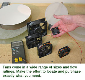 DC fans are available in a wide range of sizes. Resist the urge to use just whatever fan you have lying around, as there is a good chance it's the wrong size. Once you know where to look, fans are available in a wide variety of physical sizes and flow ratings for a few dollars.
Most electronics supply houses carry small DC fans. At least one good source is DigiKey (Digikey.com). They stock fans from several manufacturers, and their catalog lets you choose specifically the cfm and housing size you need. (If you have found another good source of fans, please contact me.)
Estimating a Fan's Flow Rate From Its Physical Size
Frequently, small DC fan don't have the flow rating indicated on the housing. If you're unsure of its flow rating, you can approximate it by measuring the housing size. Fans of a given size tend to fall into a close range of cfm ratings. If your fan size isn't exactly what is shown in the table, interpolate between values. (Note: these values are valid for 12 volt DC fans with conventional axial impeller airfoil designs.)
|
dimension (mm) |
dimension (mm) |
Approximate Flow Rate (cfm)
|
|
25
|
10
|
2-3
|
|
40
|
10
|
5-8
|
|
40
|
25
|
19-23
|
|
60
|
25
|
17-25
|
|
60
|
38
|
40-55
|
|
80
|
25
|
25-40
|
|
80
|
38
|
75-90
|
|
120
|
38
|
150-190
|
I owe thanks to the engineering team at Panasonic who provided technical information for small DC fans, and Robert Royce (R. F. Royce Precision Optical Components) who loaned me mirror blanks for cooling trials.
Return to Telescope Optics Topics.