Adventures in collimation |
| by Bryan Greer |
| Originally posted Jan. 1997. Last updated July 2, 2008. |
Home
Telescope Thermodynamics
Sept. 2000 Sky & Telescope magazine companion web site
May & June 2004 Sky & Telescope magazine companion web site
Using fans with a Newtonian telescope
Tips on attaching a temperature probe to your telescope
Optical Miscellany
Try this at home!
How atmospheric seeing affects telescopes with different focal ratios
Animated focal plane illumination map
Properties of various mirror substrate materials
Adventures in collimation
|
Note: This web page is not intended to be a comprehensive overview on how to collimate telescopes. It was created to only look at one smaller issue; what should a properly collimated telescope look like when diagonal offset is incorporated. If you are searching for a more complete step-by-step site, see Mel Bartel's or Nils Olof Carlin's comprehensive collimation pages. Also, Andy's Shot Glass has a well-illustrated guide, though it might take a few minutes to download. |
Background
In 1997, an interesting discussion ensued on Mel Bartel's Amateur Telescope Makers Mailing List. The debate surrounded what the final view down the focuser of a properly collimated Newtonian telescope should look like. In particular, there was confusion about a) if all components (reflected and real) should appear concentric or not, and b) if not, what should appear non-concentric. I had enough doubt myself to cause me to generate the following set of images.
These pictures were generated using a 3-d rendering program. They are simulations of views down the focuser of a Newtonian telescope (w/o eyepiece, of course) during the collimation procedure. The vantage point is from the focal plane. The big advantage of using computer modeling is that all the positions and tilts of the optical components can be specified precisely without ambiguity. It can be difficult to determine exact spatial placements on a real telescope, and probably led to much of the confusion on the ATM Mailing List. The program easily allows experimentation with misalignments to see what they will look like in the real scope.
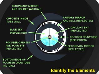
Identifying What You See
The images below closely resemble what you will see during a daylight collimation of a fast Newtonian. The modeled telescope is an 8" f/5 in a 10" ID tube. The secondary mirror is 2.00" minor axis. The focuser drawtube is 1-1/4" dia. The mirror clips, cell mounting, and other components have been included for clarity and realism. Note that the proper offset for a scope of this design is about 0.1" towards the primary and away from the focuser.
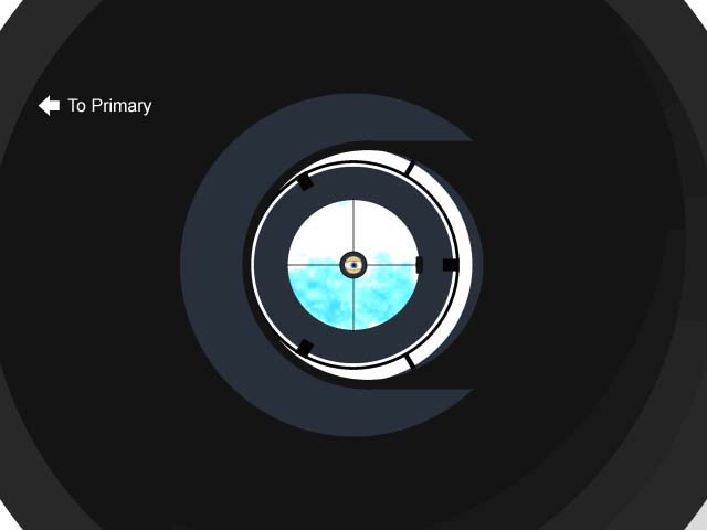
Trial 1: All Optical Components Physically Centered
As a first go at it, the geometric center of the secondary mirror is located exactly under the focuser centerline and along the optical axis of the primary (that is, no offset in either direction). The secondary mirror is tilted precisely 45 degrees with respect to the optical axis. Note that perspective gives the illusion that the secondary is shifted to the right (away from the primary). The decentered reflection of the primary mirror reveals that we are not intercepting the light cone symmetrically.
It should be pointed out that this is not how most people would leave the collimation in a scope without offset. A natural consequence of the collimation procedure would result in adjusting the tilt of the secondary (it would no longer be at exactly 45 degrees) and primary mirror (it would no longer be pointed exactly down the middle of the tube) in order to center the reflection of the primary mirror within the secondary mirror. However, this view confirms what most of us already know; the light cone would not be symmetrically intercepted when the optical components are centered with the secondary at a 45-degree angle.
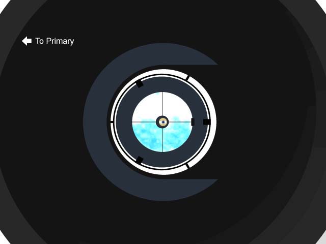
Trial 2: Offsetting 0.10" Towards the Primary
The secondary mirror is now shifted 0.1" towards the primary, though it's still centered in the tube (i.e., not shifted away from the focuser). The secondary visually appears to be directly under the focuser, even though the true geometric center of the secondary is not. This may sound counterintuitive to some, but again, it is due to perspective (i.e., the lip of the secondary that is furthest away looks smaller).
Strangely, the reflected image of the focuser hole (the human eye in the center) is no longer centered in the reflected image of the secondary (dark gray circle around it). The primary mirror is better centered in the real image of the secondary, revealing that we are intercepting more of the light cone. However, the image is still not completely concentric, indicating the need for offset in the other direction (away from the focuser).
Just about everybody who claims they don't incorporate offset into their telescope designs has actually done this partial offset without realizing it. Just by "centering" the secondary in the site tube tool, they have shifted the secondary towards the primary by the offset distance. Perspective takes care of this for us.
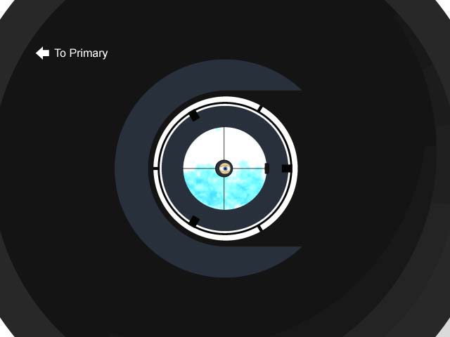
Trial 3: Final Collimation-Offsetting 0.10" In Both Directions
Now the secondary is offset in both directions (0.1" towards primary and 0.1" away from focuser). This would be considered proper collimation for a Newtonian with full offset incorporated. Note that the reflected image of the primary mirror and cell is centered and concentric. We are now intercepting the light cone symmetrically and will not experience asymmetric vignetting of the field.
However, it is important to recognize that all reflected components are not concentric. Specifically, 1.) the reflected human eye image is not centered within the secondary reflection, and 2.) the reflected image of the spider and secondary holder appear slightly shifted to the left within the open end of the tube (it's subtle, but you can see it). This makes sense, as the secondary mirror and spider really are shifted away from the focuser.
|
(March 2002) Additional Comments About Offsetting: I have received a few e-mails from telescope owners stating that it is not important to offset the secondary mirror in Newtonian telescopes. I completely agree! I re-read this 1997 webpage, and I can see where one could interpret this as an encouragement to implement offset. That was not my intention. I only wanted to confirm to myself what the view down into the optics would look like if the secondary was offset. As many of you have pointed out, offsetting the secondary only affects the final orientation of the optical axis with respect to the physical axis of the telescope tube. If you do not offset, the only consequence is that the primary mirror will not be pointed exactly down the center of the tube by a small fraction of a degree. This poses no problems optically, and has no adverse affect on collimation or vignetting, but with one exception listed below. Without offset and proper collimation, the wavefront will still be perpendicular and centered within the focuser drawtube, and this is the definition of perfect collimation. That said, there are two valid reasons to offset. First, German equatorial mounts (GEM) with computerized GOTO control assume the optical axis and mechanical axis are parallel, and that the R.A. and declination axis are perpendicular. If they're not, there will be a pointing error after slewing to an object. If your Newtonian will be mounted on a GOTO-equipped GEM, you will want to implement full and accurate offset. While it's still not critical, it is not a bad idea to offset the secondary mirror in large truss-style Newtonian scopes. This is because the inside diameter of the upper cage assembly is frequently barely larger than the primary mirror itself. If the primary mirror is not pointed exactly down the center of the telescope, asymmetrical vignetting will result from one edge of the cage assembly obscuring the incoming light rays. (Asymmetrical vignetting is a condition where one edge of the field of view is darkened more than the opposite side.) Undoubtedly, this lopsided vignetting would be unnoticeable to the naked eye (the eye is a notoriously "nonlinear" detector of light level), but it could conceivably show up in photography where a much larger portion of the focal plane is used. |
Return to Telescope Optics Topics.